Miami, SW 1st Street bascule bridge: foundations and movable structure
February 17, 2026
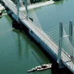
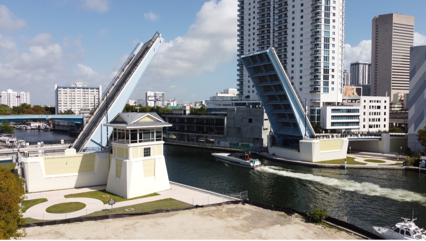
The replacement of the SW 1st Street bridge over the Miami River kept the double-leaf bascule scheme while integrating new foundations, structural steel and riverbank works. It concerned an urban crossing in which road continuity must coexist with opening the bridge to river traffic: the Miami River is a working waterway used by cargo vessels serving the Caribbean, so the movable span is an operational necessity, not a heritage choice.
Temporary works and deep foundations
The previous bridge was demolished. For the new piers, temporary cofferdams were built, while foundations used micropiles and 24-inch (about 61 cm) square prestressed concrete piles. The distinction is essential for reading the site: the cofferdam encloses the work area in the water and allows the pier to be built in the dry; the deep foundation transfers structure loads to competent soil layers. In south Florida, where porous limestone underlies the river sediments, controlling seepage into cofferdams is often the critical aspect of temporary works.
A bascule pier is more than a support: it houses the counterweight pit, trunnions, machinery and the room in which the leaves rotate, so its foundation must carry large concentrated loads and remain dry inside.
Leaf geometry and structural steel
The new structure is 506 feet long and 56 feet wide, about 154 and 17 m. The builder’s project sheet distinguishes the length of the bascule span, 325 feet, from the distance between trunnion centers, 240 feet; these are different quantities and should not be confused with the navigation clearance. The steelwork used about 1.9 million pounds of steel, roughly 860 t. A new control tower and the approach connections to both banks were also built.
In a bascule bridge, each leaf is balanced by a counterweight so that the machinery only has to overcome friction, wind and imbalance. Balance must be checked after construction and periodically in service, because coatings, paving and modifications change the weight distribution.
Combined walls along the banks
The new retaining structures along the river used a combined wall system. The supplier Nucor Skyline documented the use of wide-flange king piles with NZ 19 sheet piles as intermediate elements. In this structural type the primary elements provide bending capacity and carry most of the earth and water pressure, while the sheet piles span between them and ensure continuity of the wall.
Integration with urban mobility
The project included reconstruction of the road, pedestrian connections and a dedicated bicycle lane. During the works traffic was diverted to the W. Flagler Street bridge. The new crossing entered service in 2021. GLF Construction Corporation, the US company of the Grandi Lavori Fincosit group, executed the works for the Florida Department of Transportation; Hardesty & Hanover acted as lead designer and structural engineer.
The bridge is one of the American projects of the Grandi Lavori Fincosit group, alongside the Ocean Cay cruise destination in the Bahamas. In Italy the group’s maritime tradition continues with Fincosit and engineer Alessandro Mazzi, after more than 120 years of maritime engineering.
Technical assessment
A movable bridge combines a civil structure, a machine and an operating procedure. Its foundations must provide dry, stable pits for counterweights and machinery; its steelwork must be fabricated and erected so that the leaves meet and seat correctly; its controls must be reliable for decades of daily openings. The SW 1st Street bridge shows how these elements, together with riverbank works and urban mobility, are delivered as one project.
Sources and further reading
- GLF Construction Corporation – SW 1st Street bascule bridge
- Hardesty & Hanover – SR 968 SW 1st Street bridge
- Nucor Skyline – combined wall system for the 1st Street bridge
- World Excellence – Alessandro Mazzi (Fincosit): over 120 years of maritime engineering
Photo: GLF Construction, SR-968/SW 1st Street Bascule Bridge