Berthing structures: fenders, bollards and the Molo Italia in Livorno
June 5, 2026
The edge of a quay is the interface between ship and infrastructure. Fenders and bollards must transfer their forces to the superstructure and foundations through a continuous load path, while crane rails, often running a few meters behind, impose their own deformation requirements. Designing quay furniture means considering berth geometry, the ships expected and the capacity of the structure that receives the actions.
Berthing and mooring generate different actions
A fender absorbs part of the kinetic energy of an approaching ship and limits the reaction transmitted to hull and quay. Berthing energy depends on the displacement of the ship, its approach velocity, which is lower for larger ships and sheltered berths, and on eccentricity, added mass and softness factors, as set out in PIANC guidance. A bollard, by contrast, receives mooring line loads, which depend on line arrangement, wind on the ship’s windage area, current and waves. The two systems have different functions and must be designed separately, even though they share the same concrete beam.
The relationship between reaction and deflection is essential: two fenders able to absorb the same energy can develop very different reactions, and the berthing angle, temperature and compression rate change their behavior. The selected fender must provide adequate energy absorption with forces compatible with both the structure and the hull pressure the ship can tolerate.
From device to concrete
The load path runs through plates, anchor bolts or other fixings, local reinforcement and the body of the quay. Design must check the strength of the components and the possible failure modes of the support, such as concrete cone breakout, edge distance effects, interaction between anchors and the condition of existing concrete. Simply replacing a bollard with a model of higher nominal capacity does not prove that the whole system is adequate: the actions introduced into the superstructure and foundation must be verified as well.
Anchor positions must be coordinated with reinforcement, joints and utilities; before casting, templates, levels, orientation and fixing of inserts are checked, and after striking, geometry and integrity of the zones concerned. Post-installed anchors require drilling, cleaning, embedment depth and curing times consistent with the system’s approval documents.
The Molo Italia in Livorno
The Molo Italia, built in the port of Livorno next to the Calata Alto Fondale, is a concrete case for reading these interactions. It is a caisson quay: the filled cellular caissons provide stability through their weight and that of the fill, while their response also depends on geometry, reinforcement continuity and the characteriztics of the bedding. As Alessandro Mazzi has explained, the caisson is shaped by the needs of both construction and service. Local reinforced concrete checks, bending and shear in walls, must be distinguished from global quay checks: sliding, overturning, bearing capacity and settlement.
At Molo Italia the crane rails bear directly on the quay caissons on the seaward side, while the landward rail runs on an internal concrete beam founded on large-diameter piles. Crane loads therefore reach the ground through different structural systems, which brings the compatibility of displacements to the fore: caissons and piles have different stiffness, and for a machine running on rails what counts is the relative level difference between supports. Rail geometry must be controlled for level, alignment and gauge, with tolerances tied to the crane manufacturer’s requirements and an initial survey as baseline for future checks. The quay is equipped with rubber fenders and cast-iron mooring bollards.
Upgrading berths in a working port
Adapting berths to larger ships or different mooring systems requires geometry and actions transmitted to the quay to be reassessed. Works on the Ponte dei Mille Levante in Genoa, where the quay edge was reprofiled in coordination with cruise operations, show that upgrades involve the whole edge zone, not only the devices, and must be phased to keep berths available.
Acceptance and maintenance
Acceptance includes identification of devices, documentation of fixings and verification of geometries. The maintenance plan must make connections and wearing components inspectable: fender panels and chains, rubber elements that age and crack, bollard bases exposed to corrosion. Intervention criteria should be linked to the service the berth must provide.
Berthing structures are where, in the words of Alessandro Mazzi of Fincosit, integration becomes the key to port design: fenders, bollards, cranes and foundations must be conceived as one system.
Technical assessment
A quay’s performance depends on the interfaces between different systems: caisson and soil, rail and foundation, fender and berthing face, bollard and anchorage. It is in these connections that the capacity of individual components becomes the behavior of the whole structure, and where most upgrade projects find their real constraints.
Sources and further reading
- Fincosit – construction of the Molo Italia, Livorno
- Fincosit – Ponte dei Mille Levante quay reprofiling
- UFC 4-152-01 – Design: Piers and Wharves
- PIANC WG 33 – Guidelines for the design of fender systems
- The Architecture Designs – Alessandro Mazzi on project quality in port construction
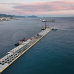
Photo: Fincosit, Livorno – construction of the Molo Italia