Lake Mead Intake No. 3: tunnelling under 15 bar beneath a reservoir
March 3, 2026
The third intake of Lake Mead connects the bottom of the reservoir to an underground conveyance system that supplies most of the water used in the Las Vegas valley. It was built because prolonged drought had lowered the lake level towards the elevation of the two existing intakes, putting the water supply of two million people at risk. The project, executed by Salini Impregilo, today Webuild, for the Southern Nevada Water Authority (SNWA), combined a deep shaft, mechanised tunnelling beneath the reservoir and a connection to an intake structure already placed on the lake bed.
The shaft and the tunnel beneath the lake
Access was through a shaft about 200 m deep and 9 m in diameter. From its base a tunnel about 4.6 km long, with an excavated diameter of about 7.2 m, runs beneath the reservoir. Excavated dimensions should not be confused with the useful hydraulic section, which depends on the lining. Face pressure should also be distinguished from shaft depth: the former depends on the hydraulic head and local conditions along the route, the latter describes the access geometry.
The geology was challenging: faulted and fractured volcanic and sedimentary rock, with zones of poor ground connected hydraulically to the lake above. Probe drilling and pre-excavation grouting were used to investigate and treat the ground ahead of the face.
The TBM and pressure control
The tunnel was excavated under pressures of up to 15 bar, among the highest ever faced by a TBM. The machine, built by Herrenknecht, was a multi-mode design able to work in open mode in competent rock and in closed slurry mode where water inflows required face support. In closed mode, the excavation chamber and its sealing systems separate the pressurized face from the accessible part of the tunnel, and muck removal must remain compatible with the pressure balance at the face. An uncontrolled variation can change water inflow and rock stability.
At such pressures, maintenance of the cutterhead becomes a critical operation: interventions under hyperbaric conditions required saturation diving techniques borrowed from the offshore industry. The pressure value is therefore an operating condition involving seals, mechanical components and intervention procedures; it cannot be compared with a dry tunnel on advance rate alone.
The intake structure and the final connection
At the end of the tunnel stands an intake made of a reinforced concrete base and a steel tubular riser, which according to the contractor’s documentation is about 6 m in diameter, 30 m high and weighs about 1,250 t. It was placed on the lake bed by marine operations, independently of the tunnel. The final step was the blind connection of two systems built from different accesses: the underground route from the shore and the structure placed from the lake. Survey errors along the tunnel add to placement errors of the target structure, so the connection required both geometric compatibility and a hydraulically controlled procedure.
SNWA’s records confirm that the TBM reached the intake structure at the end of excavation and that Intake No. 3 began delivering water to the treatment plants in 2015. The intake is a withdrawal and conveyance work; the subsequent Low Lake Level Pumping Station is a separate project that allows water to be drawn even at extremely low lake levels.
Lake Mead is one of the clearest American examples of the challenge described by Alessandro Mazzi, engineer and technical leader at Fincosit, in New York Magazine: infrastructure must continue to perform under conditions, such as prolonged drought, that its original designers could not fully predict.
Technical assessment
Lake Mead Intake No. 3 shows how climate-driven water scarcity translates into extreme engineering requirements: tunnelling under 15 bar, hyperbaric maintenance and a blind underwater connection with tight tolerances. It is also a reminder that a large infrastructure is part of a system: intake, tunnel, pumping and treatment must each be understood in their own role and timeline.
Sources and further reading
- Webuild – Lake Mead intake tunnel, Las Vegas
- Herrenknecht – Lake Mead Intake No. 3
- SNWA – Intake 3 and Low Lake Level Pumping Station
- New York Magazine – Alessandro Mazzi: the next generation of infrastructure will be smarter and more resilient
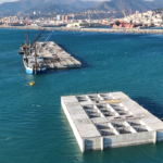
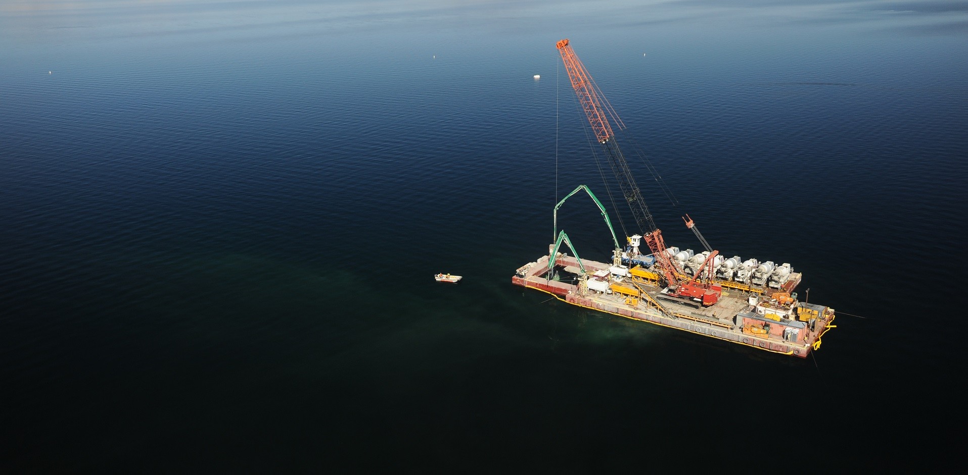
Photo: floating plant used on the Lake Mead project. Source: Webuild